

Mechanical Parts are the working elements that make machines move, connect, support, seal, or transfer force. A steel shaft carries torque through a gearbox. A bearing reduces friction around that shaft. A gear changes speed and direction, while a fastener holds two housings together under repeated vibration.
Henry Ford’s practical principle, “Nothing is particularly hard if you divide it into small jobs,” offers a useful way to understand these components. Each part has a defined function, but its performance depends on the surrounding assembly. A gear may appear simple. Its tooth profile, material hardness, lubrication, and alignment determine whether it runs smoothly or fails early.
This guide examines common types of Mechanical Parts, including structural components, power-transmission elements, fastening parts, seals, springs, and fluid-control components. It also considers the materials, tolerances, loads, and manufacturing methods behind them. These details matter. A small clearance can prevent overheating. A poor surface finish can damage a seal.
Real machines are rarely so tidy.
One component may fit several categories. A coupling joins shafts, yet it also transmits motion and absorbs misalignment. Classification can therefore vary between textbooks, manufacturers, and engineering teams. That uncertainty deserves attention, not concealment.
Reliable identification requires more than appearance. Engineers and technicians compare drawings, dimensions, material specifications, operating conditions, and inspection results. Standards such as ISO and ASME can support consistent decisions, but they do not replace professional judgment. By connecting theory with workshop realities, this article builds a clearer foundation for selecting, maintaining, and evaluating Mechanical Parts.
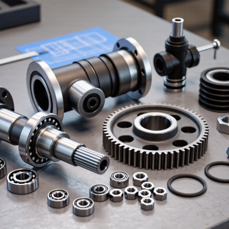
Mechanical parts include shafts, gears, bearings, fasteners, housings, and precision pins. Each part transfers motion, supports loads, or controls alignment. In practical machining, a part is not defined by shape alone. Its function also depends on measurable size limits.
ISO 286-1 and ISO 286-2 provide a global system for dimensional tolerances and fits. The system uses tolerance grades from IT01 through IT18. Smaller numbers indicate tighter control. For a nominal diameter between 30 and 50 mm, ISO 286-2 assigns approximately 25 micrometres to IT7. That is thinner than a human hair. A hole-basis fit commonly uses H for the hole, while the shaft receives a selected deviation. Clearance, transition, or interference then depends on both tolerance zones.
A quality engineer should verify these values with calibrated gauges and current drawings. Measurement uncertainty matters. A reported 25-micrometre tolerance is not automatically reliable. ISO 14253-1 requires decision rules when measurement results approach specification limits. That detail is often overlooked. So are temperature effects, burrs, coating thickness, and tool wear. The International Trade Centre’s 2023 machinery trade data also shows the global scale of mechanical equipment exchange, where consistent fit supports interchangeability across suppliers. Yet ISO 286 cannot solve every problem. Surface roughness, material expansion, and assembly force still need separate engineering controls.
Mechanical parts are individual components that transmit, support, guide, or secure motion. Their function provides a more useful classification than their shape. Fasteners hold assemblies together, including bolts, screws, nuts, washers, pins, and retaining rings. A fastener may look minor, yet incorrect preload can loosen a joint or distort a housing. During routine assembly work, I check thread engagement, contact surfaces, tightening sequence, and access for future maintenance. Small details matter. A clean thread matters.
Bearings support rotating shafts while controlling radial or axial movement. Rolling elements need suitable load ratings, accurate alignment, proper lubrication, and effective sealing. A bearing can fail early when a shaft is slightly bent or contamination enters during installation. Gears transfer torque between shafts and change speed, direction, or mechanical force. Their tooth profile, center distance, hardness, and lubrication affect performance. Unusual noise often appears before visible damage. Listening helps, but it is not a measurement.
Shafts carry torque and locate rotating parts such as gears, couplings, and pulleys. Their diameter, material, keyways, shoulders, and surface finish influence strength and fatigue life. A shaft may survive static loading yet crack under repeated bending. Parts also overlap categories: a retaining ring is both a fastener and a positioning device. Simple labels become imperfect here. Engineers should verify drawings, tolerances, loads, maintenance conditions, and safety requirements before selecting components. Inspection records should note wear patterns, looseness, heat marks, and lubricant condition. Guessing saves minutes, sometimes. It can cost a replacement assembly.
What Are Mechanical Parts and Their Types?
Mechanical parts transfer, support, guide, or control motion. Gears are especially important because they transmit torque between shafts with predictable speed ratios. The U.S. Department of Energy reports that motor-driven systems consume about 69% of industrial electricity in American manufacturing. Small transmission losses can therefore become expensive operational problems.
ISO 6336 provides a structured method for rating cylindrical gears. Its calculations examine tooth bending strength and contact stress. Engineers also consider load distribution, dynamic effects, surface finish, material quality, and safety factors. A practical assessment starts with torque, speed, duty cycle, lubrication, and operating temperature. Misalignment matters too. A perfect calculation cannot rescue poor assembly. ISO 6336-1, ISO 6336-2, and ISO 6336-3 define the key calculation principles, but real performance still depends on manufacturing accuracy and maintenance. The International Energy Agency reported that industry used roughly 37% of global final energy in 2022, making efficient power transmission increasingly relevant.
Tips: Record actual torque and temperature during operation. Check tooth contact patterns during commissioning. Do not rely only on catalogue ratings. A gear may pass a nominal ISO calculation yet fail early under shock loads, contamination, or repeated overloads. This is where engineering judgment remains necessary.
What Are Mechanical Parts and Their Types?
Mechanical parts transfer motion, carry forces, or control alignment. Common types include shafts, gears, fasteners, springs, seals, and bearings. Bearings deserve careful comparison because their failure can stop an entire assembly. During workshop inspections, I look beyond visible damage. A polished raceway may still hide fatigue. That detail matters when selecting a load-bearing component.
ISO 281 provides a consistent method for estimating rolling bearing life. Its basic rating life, L10, represents the revolutions that 90% of identical bearings can reach under defined conditions. It is not a guaranteed service interval. The calculation uses dynamic load rating C and equivalent dynamic load P. For ball bearings, life commonly follows (C/P)^3. Roller bearings often use an exponent near 10/3. A small load increase can sharply reduce predicted life. Keep this in mind.
In practice, I compare calculated life with speed, lubrication, contamination, temperature, alignment, and shock loading. ISO 281 is powerful, but real machines rarely match laboratory assumptions. A misaligned shaft can create edge stress, while thin lubricant films accelerate surface damage. I once trusted a long L10 result and overlooked frequent vibration; the component still failed early. That mistake changed my inspection routine. Load ratings help rank parts, but field evidence remains necessary. Measure actual loads. Check the installation, too.
| Mechanical Part or Bearing Type | Primary Load Capability | Typical Mechanical Applications | ISO 281 Life Exponent p | Basic Dynamic Load Rating | Equivalent Dynamic Load, P | Illustrative L10 at C/P = 10 | Main Strengths | Important Limitations |
|---|---|---|---|---|---|---|---|---|
| Single-row deep-groove ball bearing | Primarily radial loads; moderate axial loads in both directions | Electric motors, pumps, fans, conveyors, gear-driven equipment | 3 | C: basic dynamic radial load rating, expressed in newtons (N) | P = XFr + YFa when radial and axial loads are combined; coefficients depend on bearing geometry and loading conditions | 1,000 million revolutions | Low friction, high speed capability, compact design, and relatively simple installation | Less suitable for very high shock loads, major shaft deflection, or heavy misalignment |
| Angular-contact ball bearing | Combined radial and axial loads; axial capacity depends on contact angle | Machine-tool spindles, precision shafts, pumps, compressors, screw-support systems | 3 | C: basic dynamic load rating used for rolling-contact fatigue life calculations | P = XFr + YFa; paired arrangements are commonly used when axial loads act in both directions | 1,000 million revolutions | Good axial load control, high rotational accuracy, and suitability for high-speed operation | Usually requires correct mounting preload or clearance; sensitive to alignment and installation errors |
| Cylindrical roller bearing | High radial loads; some designs can accommodate axial displacement or limited axial loads | Gearboxes, rolling equipment, large electric motors, industrial transmission shafts | 10/3 | C: basic dynamic radial load rating for roller-bearing life assessment | P ≈ Fr for predominantly radial loading; axial treatment depends on flange and cage design | Approximately 2,154 million revolutions | Higher radial load capacity and greater stiffness than similarly sized ball bearings | Many designs have limited axial capacity; alignment, lubrication, and mounting accuracy are important |
| Tapered roller bearing | Combined radial and axial loads in one direction | Vehicle wheel hubs, reduction gears, material-handling equipment, heavy-duty shafts | 10/3 | C: basic dynamic load rating for the complete bearing arrangement | P = XFr + YFa; coefficients are selected according to bearing geometry and the radial-to-axial load ratio | Approximately 2,154 million revolutions | High combined-load capacity, high stiffness, and accurate control of shaft position | Usually needs an opposing bearing for axial loads in the reverse direction; preload and adjustment affect life |
| Spherical roller bearing | Very high radial loads, combined loads, and tolerance of shaft or housing misalignment | Conveyors, crushers, fans, mining machinery, heavy industrial drives | 10/3 | C: basic dynamic load rating for the rolling-element set and raceway system | P = XFr + YFa; values depend on internal design, clearance, and load ratio | Approximately 2,154 million revolutions | High load capacity and self-aligning operation where shaft and housing alignment is difficult | Generally has higher friction and lower speed capability than many ball-bearing designs |
| Thrust ball bearing | Axial loads in one or two directions, depending on the bearing arrangement | Turntables, vertical shafts, low-to-moderate-speed indexing mechanisms, light axial supports | 3 | C: basic dynamic axial load rating | P ≈ Fa for predominantly axial loading | 1,000 million revolutions | Simple axial-load support, low friction, and compact axial construction | Usually unsuitable for substantial radial loads, shaft misalignment, or high-speed operation under heavy load |
| Spherical roller thrust bearing | Very high axial loads with an ability to carry radial loads and accommodate misalignment | Heavy-duty gear drives, vertical shafts, turbines, presses, and large rotating structures | 10/3 | C: basic dynamic axial load rating for roller-based thrust service | P = XFr + YFa; the applicable factors depend on the bearing design and load direction | Approximately 2,154 million revolutions | Very high axial capacity, good stiffness, and tolerance of angular misalignment | Higher friction, greater space requirements, and more demanding lubrication and installation conditions |
| Plain sliding bearing or bushing | Radial or axial sliding support; load capacity is governed by pressure, speed, material, and lubrication | Hinges, linkages, low-speed pivots, reciprocating mechanisms, and oscillating joints | Not applicable | ISO 281 C ratings do not apply because the part does not use rolling contact | Common design checks use bearing pressure p = F/(dL) and sliding velocity rather than ISO 281 life | Not rated by ISO 281 | Simple construction, good shock tolerance, low noise, and suitability for oscillating motion | Wear life depends strongly on lubrication, material pairing, contamination, temperature, and surface finish |
Mechanical parts include shafts, gears, bearings, fasteners, housings, and linkages. Their materials and manufacturing processes determine how safely they perform. A rotating shaft may need alloy steel for strength and fatigue resistance. A lightweight housing may suit aluminum or reinforced polymer. The choice depends on load, temperature, corrosion, friction, and service life. Fit matters. Engineers should also consider cleaning methods, moisture exposure, and unexpected vibration.
Manufacturing begins with the part’s geometry and required tolerance. Turning works well for round shafts, while milling creates slots, pockets, and flat faces. Casting can produce complex housings, but it may leave internal defects or uneven surfaces. Additive manufacturing supports prototypes and unusual shapes, although surface finish and long-term strength require careful testing. Sheet forming suits thin covers and brackets. A practical design should match the process, not fight it. Tight tolerances can improve performance, yet they often increase machining time and inspection costs. A spreadsheet may recommend the cheapest material, but real service conditions can prove otherwise. Test early. Small trial parts reveal warping, tool marks, weak joints, and assembly problems before production. Designers should document material certificates, dimensional checks, and test results. Still, no process is perfect. Even experienced teams must review assumptions when loads, suppliers, or operating environments change.
Density affects the weight, inertia, and material efficiency of mechanical parts. The values shown are representative room-temperature densities commonly used for preliminary material selection.


