
Choosing a Cartesian robot in 2026 starts with the task, not a trend list. A compact XYZ unit can place components on a bench, while a wide gantry can span a production line. Both use linear motion, yet their reach, payload, speed, and mounting needs differ. Small details matter: rail spacing, cable routing, and the clearance around a workpiece can change the right choice.
Robotics pioneer Joseph Engelberger once observed, “I can’t define a robot, but I know one when I see one.” His remark concerned robotics broadly, not a ranking of Cartesian designs. Still, it points to a useful question: what must the machine do, reliably, in its real workspace? This guide compares common configurations, including two-axis pick-and-place units, three-axis XYZ systems, four-axis models with rotary motion, and gantry robots built for larger areas. The labels can overlap. That distinction is easy to miss.
We’ll look at where each type fits, what trade-offs buyers should check, and how to compare specifications without treating speed figures as guarantees. A rated payload, for example, does not tell the whole story if a long tool or off-center load stresses the axes. Simple on paper. Less simple on the factory floor. No single type suits every cell, and a neat chart cannot replace measured cycle times or a careful layout review. That is worth remembering.
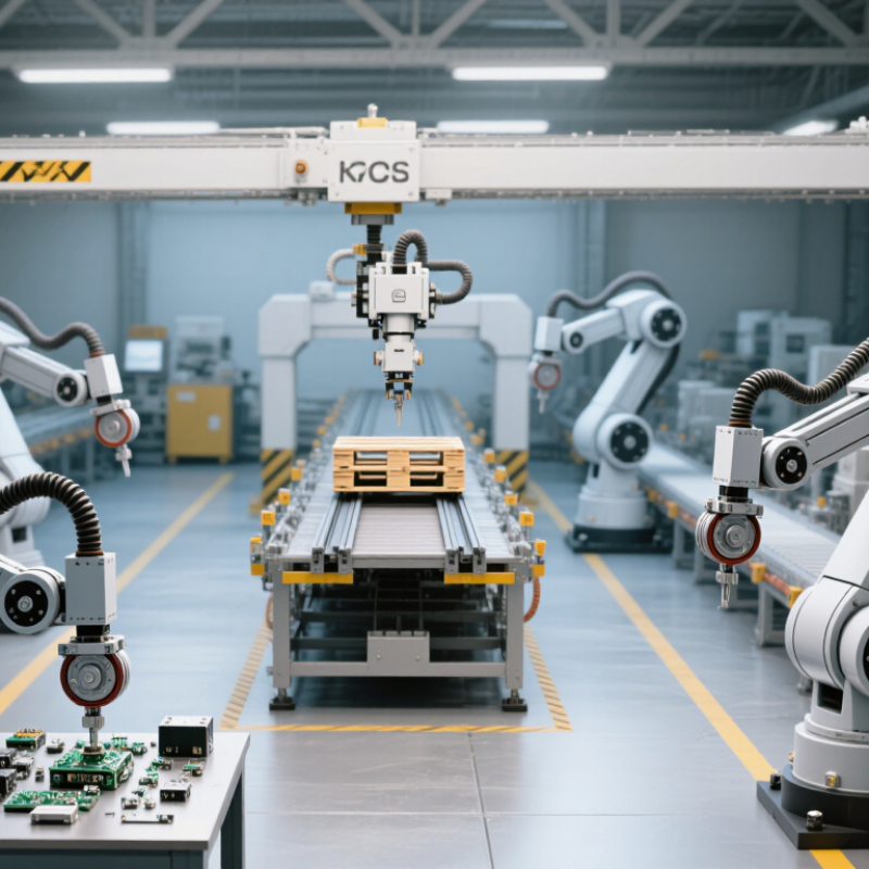
A single-axis Cartesian slide moves a load along one straight path. It suits pick-and-place transfers, part feeding, and machine loading when the start and destination stay aligned. Picture a small fixture carrying a component from a conveyor to a press. The motion is simple, but sizing is not. Engineers should check payload, stroke, speed, duty cycle, and required positioning accuracy. A long stroke or heavy load can increase deflection, so mounting stiffness matters too.
The International Federation of Robotics’ World Robotics 2024 report recorded 541,302 industrial robot installations worldwide in 2023. That figure covers industrial robots broadly, not Cartesian slides specifically. Still, it shows the scale of automation where straightforward transfer axes can serve as practical building blocks. A single axis may also pair with a robot or other equipment. Yet a straight-line move is not automatically the cheapest choice; cable routing, guarding, and maintenance access can change the real cost.
Tips: Measure the actual load, including grippers and cables. Confirm stroke and cycle time under working conditions, not just catalog ratings. Leave room for service access. A detail that is easy to miss. Recheck alignment after installation, because even a small mounting error can create uneven wear.
What Are the Top Types of Cartesian Robots in 2026?
Two-Axis Cartesian Robots: X–Y Motion for Planar Pick-and-Place
A two-axis Cartesian robot moves a toolhead along straight X and Y paths across a flat work area. This geometry suits pick-and-place tasks such as loading trays, sorting small parts, or transferring components between fixtures. Its rectangular work zone is often easier to map than a rotary arm’s reach. Repeatability still depends on frame stiffness, guide alignment, payload, and motion settings. Straight lines help. Excessive acceleration, however, can shift parts or cause frame vibration.
Tips: Keep pickup and drop-off points within the robot’s working area. Use a rigid, level mounting surface, then test with the actual part and gripper. Check cable routing across the full travel. Small snags matter.
Before choosing stroke lengths, define the required reach and cycle time. Leave clearance around fixtures, and confirm that the gripper can approach each part without scraping nearby edges. A vacuum cup may suit flat, nonporous items, while mechanical fingers can handle uneven shapes. These are starting points, not guarantees. Part variation, dust, and worn tooling can affect results. A trial with representative parts often reveals issues that drawings miss. Even a neat layout may need revision.
Three-axis Cartesian robots move along straight X, Y, and Z paths. Their axes usually sit at right angles, creating a box-shaped working area. A gantry might carry a gripper across a tray, lower it onto a fixture, then lift it clear. The motion is easy to visualize. So is the setup.
ISO 8373 describes an industrial robot as programmable in three or more axes, among other requirements. A three-axis Cartesian arrangement reaches that axis-count threshold, but axis count alone does not establish that a machine meets the full definition. Its control, reprogrammability, and intended use matter too. That distinction is easy to overlook.
In practice, these robots suit tasks with predictable routes, such as loading parts, dispensing material, or positioning sensors. Linear guides and rigid frames can support repeatable movement, but performance depends on payload, travel distance, speed, and installation. A long beam may flex slightly under load. Not ideal. Engineers should check the complete motion envelope, cable routing, and tool clearance before choosing a configuration. Cartesian motion looks simple on a drawing; real workcells rarely are.
Comparing common Cartesian configurations by number of controlled axes
A 2-axis X–Y system has two controlled axes; adding Z motion creates a 3-axis Cartesian robot, while a common 4-axis configuration adds a rotary axis. ISO 8373 describes an industrial robot as programmable in three or more axes. Axis count alone does not establish that a device meets the full definition.
Gantry robots use two or three linear axes to move a tool across a broad rectangular work area. The bridge travels along one axis, while a carriage moves across it; an optional vertical axis handles pick-and-place tasks. This layout suits large machine tending, palletizing, and inspection cells where floor-mounted arms may struggle to reach every station. Think of a long overhead beam serving several fixtures in a row. Keep the details in view: payload, travel speed, and beam deflection all affect accuracy, especially near the far end of a long span.
Scale is not a free benefit. A larger frame can need more installation space, careful leveling, and protection from dust or vibration. In its World Robotics 2024 report, the International Federation of Robotics recorded 541,302 industrial robot installations worldwide in 2023. That figure covers industrial robots generally, not gantry systems specifically, but it shows the scale of automation demand around them. For a gantry project, map the actual work envelope before choosing axis travel; unused reach adds cost and can complicate guarding. Small oversights matter. Cable routing, service access, and the load’s changing center of gravity deserve attention too. A gantry can look simple on a layout drawing. The real cell is less forgiving.
| Gantry Configuration | Linear Axes | Typical Work Envelope | Representative Payload Range | Typical Repeatability | Common Applications | Key Design Consideration |
|---|---|---|---|---|---|---|
| Planar gantry | X–Y (2 axes) | Approximately 1–10 m in X and 0.5–3 m in Y | About 5–100 kg, including end-of-arm tooling | About ±0.05–0.2 mm | Large-area dispensing, palletizing, machine tending, and material handling | Useful when motion is needed across a wide horizontal area without vertical positioning by the robot. |
| Three-axis gantry | X–Y–Z (3 axes) | Approximately 1–10 m in X, 0.5–3 m in Y, and 0.3–2 m in Z | About 5–100 kg, depending on span and axis construction | About ±0.05–0.2 mm | Pick-and-place, packaging, assembly, inspection, and loading or unloading equipment | The Z-axis adds vertical reach; longer spans and heavier loads may require larger guides or structural support. |
| Single-beam gantry | Usually X–Y or X–Y–Z | Commonly used for moderate-to-large spans; travel is configured for the application | Light to medium loads; capacity depends on beam size, span, and drive system | Application-dependent; often in the same general range as standard gantry systems | Packaging, dispensing, and general-purpose handling | A simpler frame can reduce system complexity, but beam deflection should be checked across the full span. |
| Dual-beam gantry | Usually X–Y–Z | Designed for wide or long work areas; dimensions are application-specific | Medium to heavy loads, subject to structural and drive sizing | Depends on alignment, synchronization, and mechanical design | Large-part handling, machine loading, and operations over broad work zones | Two supporting beams can improve stiffness and load distribution; coordinated drives need careful setup. |
| Long-travel gantry | Typically X–Y or X–Y–Z | Extended X-axis travel, often several metres or more | Varies widely with travel length, moving mass, and payload | Depends on axis length, drive type, and calibration | Serving multiple workstations, large-format processing, and movement between production cells | Long travel can increase settling time and structural demands; cable management and guarding also need planning. |
| Ranges are representative planning values, not guaranteed specifications or universal industry limits. Actual travel, payload, speed, and repeatability depend on span, drive technology, mounting, tooling, load distribution, and the manufacturer’s design. | ||||||
Cantilever robots use a fixed base and an arm that reaches over the work area, rather than spanning it on both sides. Two-axis models handle simple pick-and-place moves; three-axis versions add vertical travel for loading, dispensing, or inspection. Their open-sided frame can fit beside a conveyor or machine, where floor space is tight. The reach is useful. So is the clear access. But the projecting arm can flex under load, affecting accuracy at full extension.
The International Federation of Robotics reported 4,281,585 industrial robots in operation worldwide at the end of 2023 in World Robotics 2024. That figure covers all industrial robot types, not cantilever units specifically; it signals the scale of automation, not this design’s market share. For a 2026 application, compare payload, stroke, cycle speed, and repeatability at the actual working reach. Check cable routing and guarding, too. A compact frame may simplify installation, yet it can limit access from certain directions. One practical test: run the heaviest part through the longest move, then measure settling time. Catalog figures alone can miss that detail.