|
High-Speed Six-Axis Industrial Arm
Guarded operation
|
High-throughput assembly, welding, machine tending, palletizing, and material handling where people are normally separated from the robot.
|
Payload: commonly 5–300 kg
Reach: commonly 0.6–3.2 m
Operating mode: automatic, high-speed motion
|
Crushing, trapping, impact, ejection of workpieces, unexpected restart, and hazards from tooling or peripheral equipment.
|
Fixed or safeguarded perimeter; interlocked gates; safety-rated protective stops; emergency-stop functions; restart prevention; safe speed and safe position monitoring where required; validated access-control logic.
|
Apply the robot and application safety requirements to the integrated cell, including safeguarding, control-system safety, operating modes, maintenance access, and validation.
|
Usually not selected for unrestricted person-robot contact. The biomechanical contact and force guidance becomes relevant only when contact is intentionally permitted or cannot be fully excluded.
|
Choose this design when productivity, reach, payload, or process energy requires separation. Do not remove guarding solely because the arm is marketed as collaborative.
|
|
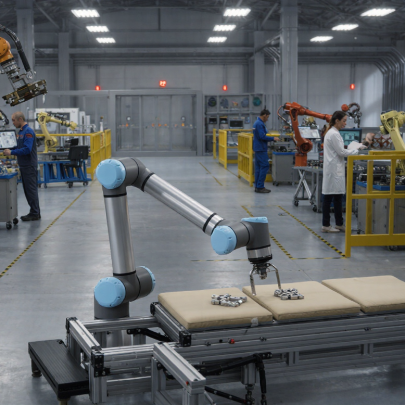
Collaborative Lightweight Six-Axis Arm
Contact-limited design
|
Low-to-medium payload assembly, inspection, kitting, packaging, screwdriving, and flexible workstation tasks with planned human interaction.
|
Payload: commonly 2–20 kg
Reach: commonly 0.5–1.8 m
Operating mode: collaborative or reduced-speed operation
|
Contact with links, joints, end effectors, workpieces, sharp edges, pinch points, unexpected motion, and ergonomic risks.
|
Safety-rated monitored stop; hand-guiding controls where applicable; speed and separation monitoring; power and force limiting; enabling device for special modes; reduced-speed setup; tool and workpiece risk controls.
|
Confirm that the complete robot application—not just the arm—supports the selected collaborative operating mode and its protective measures.
|
Use the contact-force, pressure, speed, and separation concepts as applicable to the task. Body region, contact type, geometry, tooling, and workpiece mass must be considered.
|
Select when interaction provides measurable operational value. A collaborative arm still requires a risk assessment, safeguarding of residual hazards, and validation under actual production conditions.
|
|
Parallel or Delta Robot
High-cycle handling
|
High-speed picking, sorting, dispensing, and packaging of lightweight products in a defined work envelope.
|
Payload: commonly below 10 kg
Reach: commonly 0.3–1.6 m
Operating mode: very high cycle rate
|
Fast moving links, moving tooling, falling products, access through openings, and collision with conveyors or fixtures.
|
Full perimeter safeguarding; interlocked access doors; presence-sensitive devices where justified; safe motion monitoring; controlled restart; mechanical retention of tools and products; restricted access to the envelope.
|
Evaluate the complete robot cell, especially reach-through access, stopping performance, safeguarding distances, and interaction with conveyors and feeders.
|
Contact-limiting operation is generally difficult because of high speed and moving mass. If human access is possible, the risk assessment must justify the selected protective strategy.
|
Prefer this design for speed and repeatability rather than direct human collaboration. Use guarded automation unless a validated alternative provides equivalent risk reduction.
|
|
SCARA Robot
Planar precision
|
High-speed insertion, electronic assembly, dispensing, screwdriving, and small-part handling on a horizontal workplane.
|
Payload: commonly 1–20 kg
Reach: commonly 0.3–1.0 m
Operating mode: high-speed planar motion
|
Horizontal arm sweep, vertical-axis crushing, tooling hazards, ejected parts, and access to the work envelope from above or below.
|
Interlocked guarding or appropriately positioned protective devices; safe stopping; restricted access to the sweep area; tool guarding; safe setup mode; restart prevention.
|
Address the robot, tooling, fixtures, feeder, and transfer equipment as one application. Verify stopping behavior and access protection in all operating modes.
|
Apply contact assessment only if person-robot interaction is deliberately allowed. High velocity, sharp tooling, and small contact areas can remain hazardous even at low payload.
|
Choose for compact, fast, precise planar tasks. Do not assume that a small footprint means low risk.
|
|
Cartesian or Gantry Robot
Large work envelope
|
Large-format loading, CNC tending, palletizing, dispensing, additive manufacturing, and linear transfer operations.
|
Payload: commonly 5–1,000+ kg
Reach: commonly 1–20+ m per axis
Operating mode: linear multi-axis motion
|
Crushing between axes, trapping at end stops, falling loads, suspended tooling, unexpected linear travel, and access beneath or beside the structure.
|
Perimeter guarding; access interlocks; safety-rated axis limits; safe torque or energy removal where applicable; controlled descent or load retention; emergency stop; maintenance isolation and lockout procedures.
|
Consider the complete installation, including structural elements, axis drives, suspended loads, access points, and foreseeable maintenance activities.
|
Normally selected for separated operation. Contact-limiting claims require application-specific evidence because large moving masses and long travel distances can produce serious hazards.
|
Select when the process needs long travel, high payload, or rectangular coverage. Plan safeguarding and maintenance access before finalizing the layout.
|
|
Mobile Manipulator
Mixed indoor navigation
|
Internal logistics, machine tending, inspection, transport, and manipulation across multiple workstations.
|
Payload: commonly 2–50 kg
Travel: facility-dependent
Operating mode: autonomous, supervised, or collaborative
|
Vehicle collision, trapping against fixed objects, arm motion, dropped loads, navigation errors, loss of localization, and interaction with pedestrians.
|
Protective fields; speed and separation monitoring; safety-rated obstacle detection where applicable; emergency stop; safe stop on loss of localization or protective function; restricted zones; load retention and stability controls.
|
Integrate robot-arm safety with mobile-platform safety, route controls, workstation interfaces, operating modes, and foreseeable interactions with people and other equipment.
|
Useful when person-robot contact is possible, but contact limits do not address vehicle collision, trapping, falling loads, or sharp tooling. These hazards need separate controls.
|
Choose only when the facility can support reliable traffic rules, mapped safety zones, charging arrangements, and clear responsibility for shared workspaces.
|
|
Dual-Arm or Multi-Arm Cell
Coordinated motion
|
Complex assembly, synchronized handling, two-sided processing, and operations requiring multiple manipulators or coordinated tools.
|
Payload: application-dependent
Reach: overlapping work envelopes
Operating mode: coordinated automatic or collaborative operation
|
Arm-to-arm collision, trapping between robots, shared-tool hazards, synchronization faults, dropped workpieces, and unexpected motion after a single-arm fault.
|
Coordinated safety monitoring; safe workspace and position limits; protective stops; interlocked access; validated fault response for every arm; synchronized restart; collision and pinch-point assessment.
|
Validate the integrated application and all operating modes, including interactions among robots, tooling, fixtures, and human operators.
|
Contact assessment must consider combined motion, relative velocity, tool geometry, workpiece retention, and possible contact between multiple moving components.
|
Choose for process flexibility or complex handling. If the work envelopes overlap, treat the cell as a coordinated system rather than independent robots.
|
|
Washdown or Hygienic Robotic Arm
Contamination-controlled
|
Food, pharmaceutical, medical-device, or other processes requiring frequent cleaning, corrosion resistance, or controlled contamination.
|
Payload: commonly 2–50 kg
Reach: commonly 0.5–2.0 m
Operating mode: guarded or collaborative, depending on task
|
Standard mechanical hazards plus cleaning chemicals, water ingress, slippery surfaces, corrosion, damaged seals, and contamination from lubricants or materials.
|
Safety controls rated for the environmental conditions; protected sensors; emergency stop; safe stopping; hygienic guarding and drainage; chemical and electrical compatibility checks; maintenance isolation.
|
Verify that safety functions remain dependable throughout production, cleaning, inspection, and maintenance conditions.
|
Contact limits do not replace hygiene, chemical, electrical, or process controls. Tool and surface geometry must still be assessed for contact hazards.
|
Choose when environmental resistance is a primary requirement. Confirm that safety devices and protective measures are suitable for washdown and cleaning regimes.
|